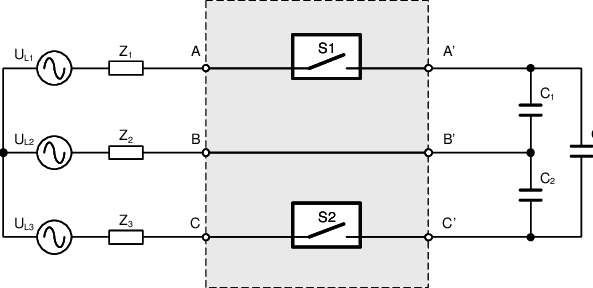
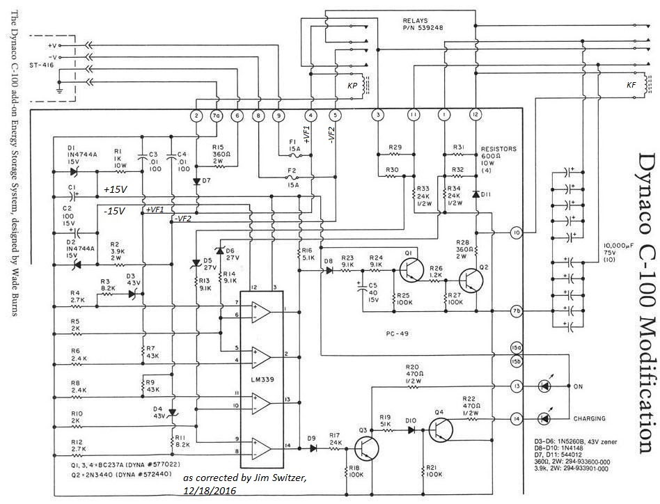
3 Phase Capacitor Bank Wiring Diagram

Vt Commodore Ignition Wiring Diagram, Complete Wiring Diagrams For Holden Commodore VT, VX, VY, VZ, VE, VF, 5.36 MB, 03:54, 32,796, John Amahle, 2018-08-01T19:37:41.000000Z, 19, Vt Commodore Ignition Wiring Diagram, to-ja-to-ty-to-my-to-nasz-swiat.blogspot.com, 1272 x 1800, jpeg, bcm pcm 12j swiat nasz, 20, vt-commodore-ignition-wiring-diagram, Anime Arts
The diagrams below show capacitor connections for typical starting circuits for reduced voltage motor controllers. Make sure that the circuit matches the actual motor diagram before applying capacitors. Improper connection may result in damage to the motor and capacitors. The capacitors should be connected on the load side of the main contacts.
Conductor size can be determined from a wire size chart. The diagrams below show capacitor connections for typical starting circuits for reduced voltage motor controllers. A vehicle wiring diagram is a. So, 3 phase capacitor bank wiring diagram using two connections is discussed below. All these are connected in delta. Each component ought to be placed and linked to different parts in. So if we employ a delta connection at high voltage, then the capacitor’s voltage rating must be high. Take one terminal of the resistor, an wiring a capacitor to start a motor begins with the connection of the positive termi. Screwdriver wire stripper wire nuts you must match the wiring to the both the motor nameplate specific.
☑ Connection 3 Phase Capacitor Bank Wiring Diagram

power factor capacitor bank connection diagram,how to connect three phase power factor capacitor

3 Phase Capacitor Bank Wiring Diagram

3 Phase Capacitor Bank Wiring Diagram

3 Phase Capacitor Bank Wiring Diagram

☑ Connection 3 Phase Capacitor Bank Wiring Diagram

Power Factor 3 Phase Capacitor Bank Wiring Diagram - Electronic Diagram

3 Phase Capacitor Bank Wiring Diagram - Seputar Bank

Connection 3 Phase Capacitor Bank Wiring Diagram - Electronic Diagram

3 Phase Capacitor Bank Wiring Diagram
