5 Wire Proximity Sensor Wiring Diagram

Vt Commodore Ignition Wiring Diagram, Complete Wiring Diagrams For Holden Commodore VT, VX, VY, VZ, VE, VF, 5.36 MB, 03:54, 32,796, John Amahle, 2018-08-01T19:37:41.000000Z, 19, Vt Commodore Ignition Wiring Diagram, to-ja-to-ty-to-my-to-nasz-swiat.blogspot.com, 1272 x 1800, jpeg, bcm pcm 12j swiat nasz, 20, vt-commodore-ignition-wiring-diagram, Anime Arts
Three wire sensors are used in various applications from detecting parts to locating position of the actual machine. 5 wire ac proximity switch diagram wiring diagram. They can come in all different technologies such as inductive photoelectric and capacitive just to list a few. 2 wire dc proximity sensor wiring diagram.
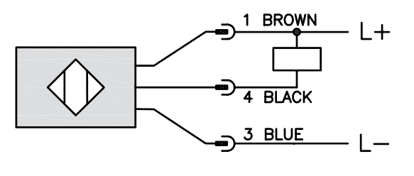
8 pin throttle position sensor wiring diagram. Read or download 5 wire proximity sensor wiring diagram for free at 223313. accnet. fr using arduino. The brown wire is the +vdc wire that connects to the positive (+) side of the power supply and the blue wire is connected to the common terminal of the power supply; Inductive sensors electrical connections. Proximity sensors malfunctions occur by wiring mistake faq singapore omron ia. Difference between pnp and npn when describing 3 wire connection of a sensor. Npn and pnp proximity sensors omch. China normally open proximity switch magnetic 2 wire or 3 reed sensor inductance position. 5 wire mass air flow sensor wiring diagram 5 wire mass air flow sensor wiring diagram.
5 Wire Proximity Sensor Wiring Diagram - Wiring Diagram Networks

5 Wire Proximity Sensor Wiring Diagram - Wiring Diagram Networks

5 Wire Proximity Sensor Wiring Diagram

5 Wire Proximity Sensor Wiring Diagram - Wiring Diagram Networks

5 Wire Proximity Sensor Wiring Diagram - Wiring Diagram Networks

5 Wire Proximity Sensor Wiring Diagram - Wiring Diagram Networks

5 Wire Proximity Sensor Wiring Diagram - Wiring Diagram Networks

5 Wire Proximity Sensor Wiring Diagram

5 Wire Proximity Sensor Wiring Diagram - Fuse & Wiring Diagram

5 Wire Proximity Sensor Wiring Diagram - Wiring Diagram Networks
